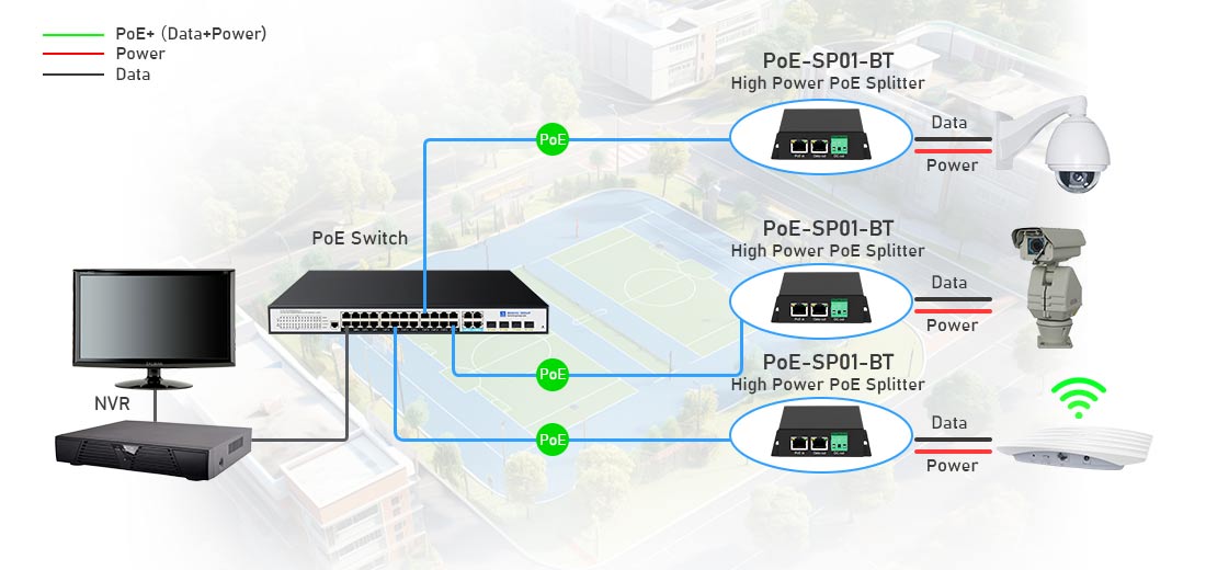
A PoE splitter extracts power and data from a PoE-enabled Ethernet cable and converts the power to a lower voltage (e.g., 5V, 9V, 12V, or 24V) to support non-PoE devices. Below is a step-by-step guide on how to connect a PoE splitter to your network and device.
1. Required Components
Before setting up, ensure you have the following:
--- PoE source – A PoE switch or PoE injector (must match the required PoE standard).
--- PoE splitter – Supports the correct power output (e.g., 12V for an IP camera).
--- Ethernet cables – Cat5e, Cat6, or better (standard length limit is 100m).
--- Non-PoE device – The device requiring power (e.g., an IP camera, access point, or media converter).
2. Connection Steps
Step 1: Connect the PoE Splitter to the PoE Network
--- Plug one end of an Ethernet cable into the PoE switch or PoE injector.
--- Connect the other end of the Ethernet cable to the PoE input port on the splitter.
--- This cable carries both power and data from the PoE source.
Step 2: Connect the Splitter to the Non-PoE Device
The PoE splitter has two output connections:
--- Ethernet Output (Data Only, RJ45) – Connect this to your non-PoE device's network port.
--- DC Power Output (Barrel Jack or Terminal Wires) – Plug this into the power input of your device.
--- Ensure that the splitter's voltage output matches the input requirement of your device (e.g., if your IP camera requires 12V DC, set the splitter to 12V if adjustable).
Step 3: Power Up the System
--- Once all connections are made, the PoE switch or injector will automatically send power through the Ethernet cable.
--- The splitter extracts the power and sends the correct voltage to the device, while data continues through the Ethernet connection.
3. Diagram of PoE Splitter Connection
PoE Switch/Injector → PoE Splitter → Non-PoE Device
4. Example Applications
Using a PoE Splitter for Different Devices
| Device Type | Recommended PoE Splitter Output | Connection Notes |
| IP Camera (Non-PoE) | 12V DC, 1A | Use the Ethernet and DC power from the splitter. |
| Wi-Fi Access Point (Non-PoE) | 9V or 12V DC | Connect the RJ45 port to the AP’s LAN port. |
| Raspberry Pi / IoT Device | 5V DC, 2A | Use a USB adapter cable if needed. |
| Media Converter | 12V or 24V DC | Connect the Ethernet for data and DC power for operation. |
5. Troubleshooting Tips
Device Not Powering On?
--- Check if the PoE switch/injector is working (try another port).
--- Ensure voltage matches the device requirement (wrong voltage can cause failure).
--- Use a compatible Ethernet cable (Cat5e or higher) to ensure proper power delivery.
Network Connection Issues?
--- If the device doesn’t get an IP address, confirm that the Ethernet connection is secure.
--- Use a Gigabit-compatible PoE splitter if your device requires 1Gbps speeds.
6. Conclusion
Connecting a PoE splitter is straightforward:
1. Connect the PoE input to a PoE switch or injector.
2. Connect the splitter's Ethernet and power outputs to the non-PoE device.
3. Verify the voltage setting matches the device requirement.
With this setup, you can efficiently power and network IP cameras, Wi-Fi APs, media converters, and IoT devices using a single Ethernet cable!